
Spike Tool Manual
CABLE SPIKING TOOL OPERATING PROCEDURE
INTRODUCTION
The SPIKE cable spiking tool is used by a lineman to help determine if any power cable that must be cut is safely de-energized. The operating procedure for SPIKE is outlined below. Please note SPIKE Tool is to be only used on single conductor cable. It is not designed for multiple conductor use.
Figures 5 shows the SPIKE parts list. Note that there is a specific sequence of steps to be followed when using SPIKE. It is mandatory to follow this sequence in order to ensure maximum safety.
The cable to be cut must be reasonably identified in the trench by means of an electronic signal, operating diagrams, etc. prior to using SPIKE. Once the cable has been identified, the cable should now be spiked as the last step, prior to cutting.
SPIKE is fired by a remote release of SPIKE’s hammer, thereby firing a spike into the center of the cable. In the event the cable is incorrectly identified and is energized, the spike creates a cable short circuit. Line protection should operate, isolating the faulted cable.
PRECAUTIONARY NOTES
The following procedures and precautionary notes are presented and should be adhered to at all times:
1. Before each use, the tool must be inspected by the operator to ensure that:
- there is no obstruction in the barrel
- all moving parts operate freely
- the tool is in a safe, clean working condition
- the hammer cap on Figure 5 #1 and the hammer cap Allen screw on Figure 5 #20 are tight
2. If the tool is defective, it should not be used, should be marked “defective” and returned to your distributor.
3. The operator of the tool shall ensure that:
- the tool is not pointed at any person at any time, whether loaded or not
- the tool is used in accordance with the instructions contained in this manual
- the tool is not loaded until it is secured on a cable
- the tool is not used where flammable or explosive substances, gases or dust are present
- all personnel are 35-40 feet away when SPIKE is being fired Click here for Lab Tests
4. If the SPIKE is being used in a manhole or similar enclosed location, do not stand inside the enclosed area when operating SPIKE. Operate SPIKE from outside the enclosed area. When SPIKE is operated in enclosed areas or indoors, ear protection must be worn in the event an energized cable is spiked
5. The SPIKE barrel shall not be removed from SPIKE’s “cable clamp”. “Barrel safety stops” have been put in place to ensure the barrel cannot be removed.
OPERATING PROCEDURE
Please follow the operating procedure below when using SPIKE:
Figure 5 shows the complete SPIKE parts list.
STEP 1
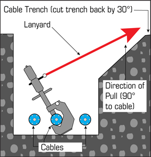
Provide clearance for the lanyard which will activate the SPIKE, by sloping one side of the trench on approximately a 30-degree angle. See Figure 1.
STEP 2
Remove SPIKE from its case and tighten it on the cable. SPIKE is secured to the cable by turning the “barrel T-handle” clockwise thereby lowering the barrel onto the cable.DO NOT LOAD THE TOOL WITH A CARTRIDGE AT THE SAME TIME.
Lean SPIKE on a 30 to 45 degree angle from the vertical. The tool should be angled away from the direction in which the lanyard will be pulled. See Figure 1.
NOTE: If the cable being spiked has a grounded concentric neutral, bond the tool using the ball stud to the concentric neutral. If the cable does not have a grounded concentric neutral, bond the tool to ground (i.e. cable tray, ground conductor, driven ground rod, or preferably system ground) using the ball stud supplied. See Figure 5, #7: Tapped mounting hole. Using the bond stud and bonding the SPIKE Tool to ground is the key part of the process. Follow all bonding and grounding procedures as required by your organization procedures or regulatory guidelines.
Figure 1
STEP 3
Remove the lanyard pin and lanyard from SPIKE’s case. Place the end of the rope with the lanyard pin attached in the trench near SPIKE. Unravel the rope and stretch it out on the ground at right angles to the trench in the direction of the pull. See Figure 1.
STEP 4
Holding the barrel of SPIKE in one hand, unscrew the breech block of SPIKE with the other hand and set it aside. Remove the cartridge holder. See Figure 2.
STEP 5
Push a spike into the barrel. Make sure the spike has a plastic centering tip on its pointed end. Re-insert the cartridge holder. Insert a cartridge of the size specified in Table 1 into the cartridge holder. See Figure 3.
Note: Cartridge selection is of vital importance. SPIKE Tool Inc. will not be held responsible for damage to equipment or personnel injuries due to incorrect cartridge selection or misuse of this tool.
STEP 6
Screw the breech block of SPIKE back onto the barrel.
Before placing the breech block back onto SPIKE, check that parts #1 and #20 are firmly in place and tight. Then turn the breech cap counter clockwise a few times and check that the firing pin is able to move freely, namely not seized. Do not screw the breech block onto the barrel if the firing pin is seized, only if it moves freely. This is a critical step in mitigating premature firing.
Recommended Cartridge Selection (Table 1)
CARTRIDGE SELECTION
CONDUCTOR RANGE
INSULATION
CABLE VOLTAGE CLASS
COPPER
ALUMINUM
#2-4/0
XLPE
5 KV to 46 KV
Brown
Brown
250 MCM-750MCM
XLPE
5 KV to 46 KV
Green
Green
1000 MCM-1500 MCM
XLPE
5 KV to 46 KV
Yellow*
Yellow
#2-4/0
Lead or
15 KV to 46 KV
Green
250 MCM-500 MCM
Aluminum
15 KV to 46 KV
Green
750 MCM-1250 MCM
Sheath or
15 KV to 46 KV
Yellow
1500 MCM-2000 MCM
Armored
15 KV to 46 KV
Yellow*
*SPIKE may not completely penetrate the conductor and project out the opposite side.
ATTENTION: Cartridge misfires may occur when the cartridge shelf life exceeds 6 months.
Table updated July 2018 as recommended by Kinetrics.
STEP 7
Prepare the tool for firing by turning the breech cap of the tool counter-clockwise until the “lanyard pin” can be inserted. Insert the lanyard pin into the appropriate pinhole located in the breech block of the tool. See Figure 4.
STEP 8
Turn the breech cap and the breech block of the tool clockwise until tightened down. If done correctly, the hammer cap in Figure 5, #1 will be protruding from the breech cap. Ensure the breech cap is well-tightened onto the breech block. The tool will not fire otherwise. SPIKE IS NOW IN FIRING POSITION
NOTE: It is the responsibility of the SPIKE operator to make sure all personnel are clear of the area before firing.
STEP 9
Carefully leave the trench, being sure not to accidentally pull the rope with your feet. Proceed to the end of the rope keeping a minimum distance of 35 feet from SPIKE. Wrap the end of the lanyard around your hand once or twice. It is mandatory that the appropriate class of rubber gloves and safety goggles be worn for this step. Fire the SPIKE by pulling on the lanyard with a snapping action. Do not use a steady pull.
STEP 10
Proceed to the trench and visually check to see if the spike is projecting from the bottom of the cable before removing SPIKE from the cable.
If the spike is projecting from the cable, except as noted in Table 1, proceed to Step 11.
If the spike is not projecting from the bottom of the cable, wait 5 minutes before handling SPIKE. While wearing the appropriate class of rubber gloves and safety goggles, remove the SPIKE Tool from the cable.
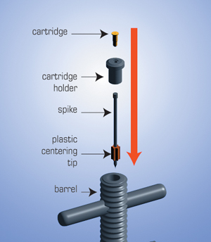
Figure 2
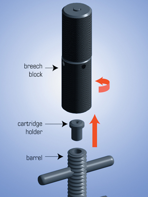
Figure 3
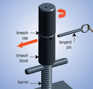
Figure 4
Remove the breech block from the barrel and remove the cartridge holder. Check to see that the barrel is clear. If it is not, then clear it with the metal ramrod provided.
After the barrel is cleared and the old cartridge is discarded, place SPIKE back on the cable and repeat steps 4 through 10. You should increase cartridge strength by one level.
STEP 11
Remove SPIKE from the cable while wearing rubber gloves, safety goggles and hearing protection.
STEP 12
Before replacing SPIKE in its case, make sure the barrel is clear and the fired cartridge is removed from the cartridge holder.
CARTRIDGE & SPIKE SPECIFICATIONS
CARTRIDGES
All cartridges used in the SPIKE are low velocity and are similar to those employed in other commercially available charge-actuated tools. Only cartridges used for low velocity tools should be substituted for the cartridges that initially come with the SPIKE. If cartridges cannot be purchased locally, they are available through the SPIKE Tool distributors listed in the Contact section of the website www.spiketool.com.
SPIKES
The SPIKE uses hardened spikes which are approximately 2” in length and ¼” head diameter. No other diameter of spike should be substituted. The spikes used have a plastic guide tip on the end. This plastic tip must be on any spike which is inserted into the barrel. Spikes for the SPIKE Tool may be ordered from distributors.
1. After each use, take SPIKE to a clean maintenance area and disassemble the tool into its two main sections. Clean and oil all moving parts.
2. Clean the barrel section of the cable clamp and ensure it is clear of all foreign material. Push a wedge of cloth 1” square cloth soaked in light machine oil through the barrel with the ramrod.
3. Wipe clean all moving parts with a lightly oiled cloth using only light machine oil.
4. Re-assemble the SPIKE Tool and place it back in the carrying case. Make sure the firing mechanism is in the unloaded position.
5. The nylon rope or lanyard was carefully chosen for its dielectric strength. Make sure it is kept clean and dry.
6. Neglecting to properly clean and oil SPIKE after use will lead to premature corrosion or may render the tool non-operational.
IMPORTANT NOTE
Only cartridges and spikes as specified in Table 1 shall be used in this tool. Cartridge selection is of vital importance. Too light a cartridge may not properly spike the cable while too heavy a cartridge may increase unnecessary wear of the SPIKE Tool. The manufacturer will not be responsible for any damage to the tool, equipment or injury of personnel resulting from incorrect cartridge and spike selection.
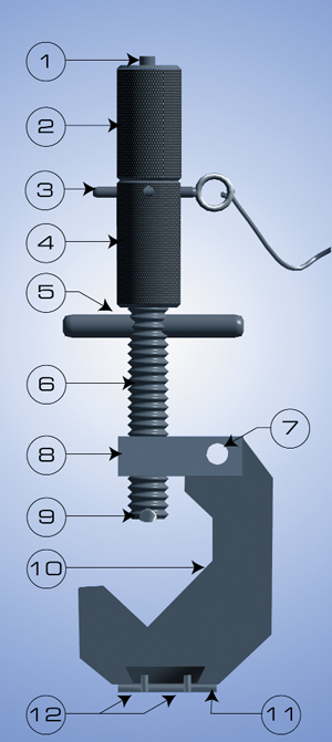
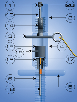
SPIKE Parts Description (figure 5)
- Hammer Cap
- Breech Cap
- Lanyard Pin & Lanyard
- Breech Block
- Barrel 'T' Handle
- Barrel
- Tapped Mounting Hole for 25mm Ball Stud (Limit: 20kA) or Split Bolt Connector 1/0 AWG Copper (Limit: 10KA) for Bonding to Ground
- Barrel Guide
- Barrel Safety Stop
- Cable Clamp
- Safety Striker Plate 3/8"
- 2 Allen Screws 5/32"
- Hammer
- Hammer Spring
- Firing Pin Assembly
- Cartridge Holder
- Power Load
- Spike
- Allen Screw 1/8"
- Allen Screw 5/64"
Updated 2021